
Ch1: Intro to Op Amps
Op Amps Table of Contents
Op Amp Basics
Operational amplifiers, also known as op amps, are semiconductor devices characterized with two high impedance inputs, a very high differential voltage gain and a low impedance output. By using external feedback components, a wide variety of different types of circuits can be built. Op amps may very well be the most useful device in analog circuitry because of the wide range of signal processing tasks it can accomplish. They are affordable, durable, and come in a wide variety of packages.
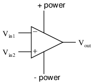
The diagram below shows the circuit symbol for a basic op amp
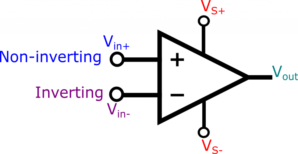
Together, the non-inverting (Vin+)pin and the inverting (Vin-)pin make up a differential input. VS+ and VS- are the positive and negative power supply respectively. And surprise, surprise Vout is the output. The general equation for the op amp relating inputs to outputs is:
[latex] V_{out}=A_{vol}[V_{(in+)}-V_{(in-)}] [/latex]
Avol is the open loop voltage gain and is typically a very big value and for an ideal op amp, it is infinite.
Video: Intro to Op Amps
To find out more, check out this video:
Op Amp Basics Practice Problems
Question 1. (Click on arrow for answer)
An operational amplifier is a particular type of differential amplifier. Most op-amps receive two input voltage signals and output one voltage signal:

Here is a single op-amp, shown under two different conditions (different input voltages). Determine the voltage gain of this op-amp, given the conditions shown:


Also, write a mathematical formula solving for differential voltage gain ([latex]A_V[/latex]) in terms of an op-amp’s input and output voltages.
File Num: 00848
Answer
[latex]A_V =[/latex] 530,000[latex]A_V = {\Delta V_{out} \over \Delta (V_{in2} – V_{in1})}[/latex]Follow-up question: convert this voltage gain figure (as a ratio) into a voltage gain figure in decibels.
Notes
The calculations for voltage gain here are not that different from the voltage gain calculations for any other amplifier, except that here we’re dealing with a differential amplifier instead of a single-ended amplifier.
A differential voltage gain of 530,000 is not unreasonable for a modern operational amplifier! A gain so extreme may come as a surprise to many students, but they will discover later the utility of such a high gain.
Question 2. (Click on arrow for answer)
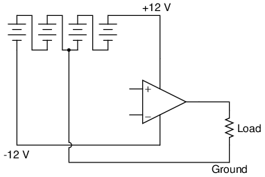
Many op-amp circuits require a dual or split power supply, consisting of three power terminals: +V, -V, and Ground. Draw the necessary connections between the 6-volt batteries in this schematic diagram to provide +12 V, -12 V, and Ground to this op-amp:

File Num: 00880
Answer
Notes
I encourage your students to learn how to power op-amp circuits with interconnected batteries, because it really helps to build their understanding of what a “split” power supply is, as well as allow them to build functioning op-amp circuits in the absence of a quality benchtop power supply.
Question 3. (Click on arrow for answer)
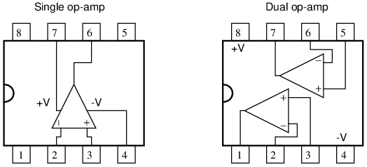
The 8-pin Dual-Inline-Package (DIP) is a common format in which single and dual operational amplifiers are housed. Shown here are the case outlines for two 8-pin DIPs. Draw the internal op-amp connections for a single op-amp unit, and for a dual op-amp unit:

You will need to research some op-amp datasheets to find this information. Examples of single op-amp chips include the LM741, CA3130, and TL081. Examples of dual op-amp chips include the LM1458 and TL082.
File Num: 00874
Answer
Notes
Ask your students to reveal their information sources, and what specific models of op-amp they researched.
Question 4. (Click on arrow for answer)
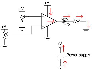
In this circuit, an op-amp turns on an LED if the proper input voltage conditions are met:

Trace the complete path of current powering the LED. Where, exactly, does the LED get its power from?
File Num: 00801
Answer
The arrows shown in this diagram trace “conventional” current flow, not electron flow:
Notes
The important thing to note here is that the load current does not pass through either of the op-amp’s input terminals. All load current is sourced by the op-amp’s power supply! Discuss the importance of this fact with your students.
Question 5. (Click on arrow for answer)
What does it mean if an operational amplifier has the ability to “swing its output rail to rail”? Why is this an important feature to us?
File Num: 00844
Answer
Being able to “swing” the output voltage “rail to rail” means that the full range of an op-amp’s output voltage extends to within millivolts of either power supply “rail” (+V and -V).
Challenge question: identify at least one op-amp model that has this ability, and at least one that does not. Bring the datasheets for these op-amp models with you for reference during discussion time.
Notes
Discuss what this feature means to us as circuit builders in a practical sense. Ask those students who tackled the challenge question to look up the output voltage ranges of their op-amp models. Exactly how close to +V and -V can the output voltage of an op-amp lacking “rail-to-rail” output capability “swing”?
Question 6. (Click on arrow for answer)
Write the transfer function (input/output equation) for an operational amplifier with an open-loop voltage gain of 100,000. In other words, write an equation describing the output voltage of this op-amp ([latex]V_{out}[/latex]) for any combination of input voltages ([latex]V_{in(+)}[/latex] and [latex]V_{in(-)}[/latex]):

File Num: 00925
Answer
[latex]V_{out} = 100,000(V_{in(+)} – V_{in(-)})[/latex]Notes
The concept of a “transfer function” is very useful, and this may be your students’ first exposure to the idea. It is a phrase used quite often in engineering applications, and may denote an equation, a table of numbers, or a graph.
In this particular question, it is important that students know how to derive and use the basic transfer function for a differential amplifier. Challenge your students to express this function in a more general form, so that calculations may be made with different open-loop voltage gains.
Question 7. (Click on arrow for answer)
How much voltage would have to be “dialed up” at the potentiometer in order to stabilize the output at exactly 0 volts, assuming the opamp has no input offset voltage?

File Num: 00924
Answer
5 volts
Notes
This question is a basic review of an ideal differential amplifier’s function. Ask your students what voltage must be “dialed up” at the potentiometer to produce 0 volts at the output of the op-amp for several different voltages at the other input. If they don’t understand at first, they soon will after discussing these alternate scenarios.
Question 8. (Click on arrow for answer)
An op-amp has +3 volts applied to the inverting input and +3.002 volts applied to the noninverting input. Its open-loop voltage gain is 220,000. Calculate the output voltage as predicted by the following formula:
[latex]V_{out} = A_V \left( V_{in(+)} – V_{in(-)} \right)[/latex]
How much differential voltage (input) is necessary to drive the output of the op-amp to a voltage of -4.5 volts?
File Num: 00926
Answer
[latex]V_{out} =[/latex] 440 voltsFollow-up question: is this voltage figure realistic? Is it possible for an op-amp such as the model 741 to output 440 volts? Why or why not?
The differential input voltage necessary to drive the output of this op-amp to -4.5 volts is -20.455 [latex]\mu[/latex]V.
Follow-up question: what does it mean for the input voltage differential to be negative 20.455 microvolts? Provide an example of two input voltages ([latex]V_{in(+)}[/latex] and [latex]V_{in(-)}[/latex]) that would generate this much differential voltage.
Notes
Obviously, there are limitations to the op-amp formula for calculating output voltage, given input voltages and open-loop voltage gain. Students need to realize the practical limits of an op-amp’s output voltage range, and what sets those limits.
Ideal Op Amp
An ideal op amp has the following characteristics:
- Infinite open loop voltage gain (Avol)
- Infinite input impedance. No current flows into inputs
- Zero output impedance. No voltage drop at output due to loads
- Infinite bandwidth. Works the same at all frequencies
- No offset voltage. When the inputs are zero, the output is zero
Real op amps are designed to be as close to the ideal op amps as possible, and in practice, you generally (but not always) have to look pretty hard to see the non-ideal characteristics of a real op amp.
Comparator
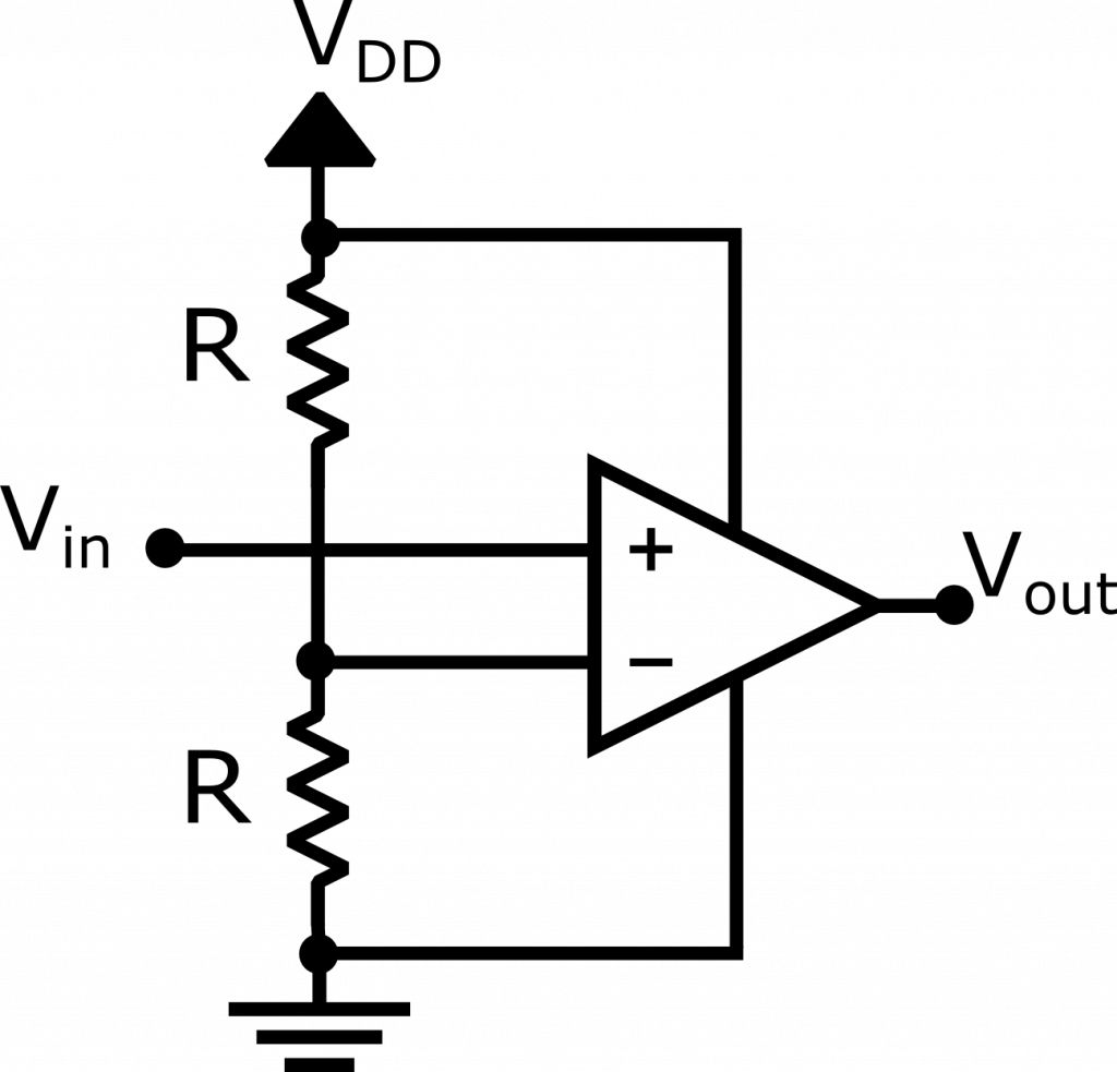
A comparator is the simplest circuit that you can build with an op amp. It uses the enormous open loop voltage gain of an op amp to indicate which of the two inputs is at a higher voltage.
Video: Op Amp Comparators
This video describes how a comparator works and provides a few examples of the different comparator configurations:
Op Amp Comparators Practice Problems
Question 1. (Click on arrow for answer)
Determine the output voltage polarity of this op-amp (with reference to ground), given the following input conditions:

File Num: 00803
Answer
In these illustrations, I have likened the op-amp’s action to that of a single-pole, double-throw switch, showing the “connection” made between power supply terminals and the output terminal.

Notes
Determining which “way” the output of an op-amp drives under different input voltage conditions is confusing to many students. Discuss this with them, and ask them to present any principles or analogies they use to remember “which way is which.”
Question 2. (Click on arrow for answer)
Determine the output voltage polarity of this op-amp (with reference to ground), given the following input conditions:

File Num: 03762
Answer
In these illustrations, I have likened the op-amp’s action to that of a single-pole, double-throw switch, showing the “connection” made between power supply terminals and the output terminal.

Notes
Determining which “way” the output of an op-amp drives under different input voltage conditions is confusing to many students. Discuss this with them, and ask them to present any principles or analogies they use to remember “which way is which.”
Question 3. (Click on arrow for answer)
In this circuit, a solar cell converts light into voltage for the opamp to “read” on its noninverting input. The opamp’s inverting input connects to the wiper of a potentiometer. Under what conditions does the LED energize?

File Num: 00872
Answer
The LED energizes under bright-light conditions, de-energizing when the light decreases below the threshold set by the potentiometer.
Follow-up question: determine what would have to be changed in this circuit to make the LED turn on when the solar cell becomes dark.
Notes
There is more than one way to accomplish the task posed by the follow-up question. Be sure to ask your students for their ideas on how to reverse the LED’s operation!
Question 4. (Click on arrow for answer)
A student is operating a simple comparator circuit and documenting the results in a table:

\settabs \+ \quad MMMM \quad & \quad MMMM \quad & \quad MMMM \quad & \quad MMMM \quad & \cr
\+ \hfill & [latex]V_{in(+)}[/latex] & [latex]V_{in(-)}[/latex] & [latex]V_{out}[/latex] \cr
\+ \hfill & 3.00 V & 1.45 V & 10.5 V \cr
\+ \hfill & 3.00 V & 2.85 V & 10.4 V \cr
\+ \hfill & 3.00 V & 3.10 V & 1.19 V \cr
\+ \hfill & 3.00 V & 6.75 V & 1.20 V \cr
\+ \hfill & [latex]V_{in(+)}[/latex] & [latex]V_{in(-)}[/latex] & [latex]V_{out}[/latex] \cr
\+ \hfill & 2.36 V & 6.50 V & 1.20 V \cr
\+ \hfill & 4.97 V & 6.50 V & 1.21 V \cr
\+ \hfill & 7.05 V & 6.50 V & 10.5 V \cr
\+ \hfill & 9.28 V & 6.50 V & 10.4 V \cr
\+ \hfill & [latex]V_{in(+)}[/latex] & [latex]V_{in(-)}[/latex] & [latex]V_{out}[/latex] \cr
\+ \hfill & 10.4 V & 9.87 V & 10.6 V \cr
\+ \hfill & 1.75 V & 1.03 V & 10.5 V \cr
\+ \hfill & 0.31 V & 1.03 V & 10.5 V \cr
\+ \hfill & 5.50 & 5.65 V & 1.19 V \cr
One of these output voltage readings is anomalous. In other words, it does not appear to be “correct”. This is very strange, because these figures are real measurements and not predictions! Perplexed, the student approaches the instructor and asks for help. The instructor sees the anomalous voltage reading and says two words: latch-up. With that, the student goes back to research what this phrase means, and what it has to do with the weird output voltage reading.
Identify which of these output voltage measurements is anomalous, and explain what “latch-up” has to do with it.
File Num: 00876
Answer
Latch-up occurs when one of the input voltage signals approaches too close to one of the power supply rail voltages. The result is the op-amp output saturating “high” even if it isn’t supposed to.
Challenge question: suppose we expected both input voltages to range between 0 and 10 volts during normal operation of this comparator circuit. What could we change in the circuit to allow this range of operation and avoid latch-up?
Notes
Ask your students what they found in their research on “latch-up,” and if this is an idiosyncrasy of all op-amp models, or just some.
Incidentally, the curved op-amp symbol has no special meaning. This symbol was quite popular for representing op-amps during their early years, but has since fallen out of favor. I show it here just to inform your students, in case they ever happen to encounter one of these symbols in an old electronic schematic.
Question 5. (Click on arrow for answer)
In this circuit, an op-amp turns on an LED if the proper input voltage conditions are met:

Trace the complete path of current powering the LED. Where, exactly, does the LED get its power from?
File Num: 00801
Answer
The arrows shown in this diagram trace “conventional” current flow, not electron flow:

Notes
The important thing to note here is that the load current does not pass through either of the op-amp’s input terminals. All load current is sourced by the op-amp’s power supply! Discuss the importance of this fact with your students.
Question 6. (Click on arrow for answer)
Trace the output waveform of this comparator circuit:

File Num: 00878
Answer
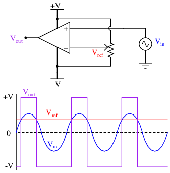
Follow-up question: explain what the phrase duty cycle means with reference to a “square” or “pulse” waveform.
Notes
During discussion, ask your students to explain how the output waveform of this comparator circuit comes to be, step by step. Ask them how they arrived at their solution, and if there is a way this AC/DC problem can be simplified to one that is DC only for easier analysis (determining what the output voltage will do for a certain set of input conditions).
Question 7. (Click on arrow for answer)
Calculate the amount of resistance that the thermistor much reach in order to turn the cooling fan on:

File Num: 04021
Answer
Thermistor resistance = 5.547 k[latex]\Omega[/latex]
Notes
Ask your students how they arrived at their solution for this question. There is definitely more than one way to do it!
Question 8. (Click on arrow for answer)
Predict how the operation of this thermostat circuit (where the cooling fan motor is supposed to turn on when the temperature gets too high) will be affected as a result of the following faults. Consider each fault independently (i.e. one at a time, no multiple faults):

- Cable fails open:
- Comparator [latex]U_1[/latex] fails with output saturated positive:
- Resistor [latex]R_1[/latex] fails open:
- Capacitor [latex]C_1[/latex] fails shorted:
- Transistor [latex]Q_1[/latex] fails shorted (drain-to-source):
For each of these conditions, explain why the resulting effects will occur.
File Num: 03768
Answer
- Cable fails open: Fan turns on and never turns off.
- Comparator [latex]U_1[/latex] fails with output saturated positive: Fan turns on and never turns off.
- Resistor [latex]R_1[/latex] fails open: Fan refuses to turn on.
- Capacitor [latex]C_1[/latex] fails shorted: Fan refuses to turn on, transistor [latex]Q_1[/latex] likely fails due to overheating when it tries to energize fan.
- Transistor [latex]Q_1[/latex] fails shorted (drain-to-source): Fan turns on and never turns off.
Notes
The purpose of this question is to approach the domain of circuit troubleshooting from a perspective of knowing what the fault is, rather than only knowing what the symptoms are. Although this is not necessarily a realistic perspective, it helps students build the foundational knowledge necessary to diagnose a faulted circuit from empirical data. Questions such as this should be followed (eventually) by other questions asking students to identify likely faults based on measurements.
Question 9. (Click on arrow for answer)
Predict how the operation of this thermostat circuit (where the cooling fan motor is supposed to turn on when the temperature gets too high) will be affected as a result of the following faults. Consider each fault independently (i.e. one at a time, no multiple faults):

- Cable fails open:
- Comparator [latex]U_1[/latex] fails with output saturated positive:
- Resistor [latex]R_1[/latex] fails open:
- Cable fails shorted:
- Transistor [latex]Q_1[/latex] fails shorted (drain-to-source):
For each of these conditions, explain why the resulting effects will occur.
File Num: 03769
Answer
- Cable fails open: Fan turns on and never turns off.
- Comparator [latex]U_1[/latex] fails with output saturated positive: Fan refuses to turn on.
- Resistor [latex]R_1[/latex] fails open: Fan refuses to turn on.
- Cable fails shorted: Fan refuses to turn on.
- Transistor [latex]Q_1[/latex] fails shorted (drain-to-source): Fan turns on and never turns off.
Notes
The purpose of this question is to approach the domain of circuit troubleshooting from a perspective of knowing what the fault is, rather than only knowing what the symptoms are. Although this is not necessarily a realistic perspective, it helps students build the foundational knowledge necessary to diagnose a faulted circuit from empirical data. Questions such as this should be followed (eventually) by other questions asking students to identify likely faults based on measurements.
Question 10. (Click on arrow for answer)
Explain what a window comparator circuit is (sometimes called a window discriminator), and identify at least one practical application for one.
File Num: 03838
Answer
A “window comparator” circuit detects when a voltage falls between two different reference voltages. I’ll let you figure out some practical applications for such a circuit!
Notes
Ask your students where they found the answer for this question, and further explore some of the practical applications they offer.
Schmitt Trigger

Schmitt triggers are comparators with some built in hysteresis so that small changes around the input threshold are ignored.
Video: Schmitt Triggers
To find out more, check out this video:
Schmitt Trigger Practice Problems
Question 1. (Click on arrow for answer)
Determine the “trip” voltage of this comparator circuit: the value of input voltage at which the opamp’s output changes state from fully positive to fully negative or visa-versa:

Now, what do you suppose would happen if the output were fed back to the noninverting input through a resistor? You answer merely has to be qualitative, not quantitative:

For your information, this circuit configuration is often referred to as a Schmitt trigger.
File Num: 02294
Answer
With no feedback resistor, the “trip” voltage would be 9.21 volts. With the feedback resistor in place, the “trip” voltage would change depending on the state of the opamp’s output!
Follow-up question: describe what effect this changing “trip” voltage value will have on the operation of this comparator circuit.
Notes
Schmitt trigger circuits are very popular for their ability to “cleanly” change states given a noisy input signal. I have intentionally avoided numerical calculations in this question, so that students may concentrate on the concept of positive feedback and how it affects this circuit.
Question 2. (Click on arrow for answer)
A comparator is used as a high wind speed alarm in this circuit, triggering an audio tone to sound whenever the wind speed exceeds a pre-set alarm point:

The circuit works well to warn of high wind speed, but when the wind speed is just near the threshold level, every little gust causes the alarm to briefly sound, then turn off again. What would be better is for the alarm to sound at a set wind speed, then stay on until the wind speed falls below a substantially lower threshold value (example: alarm at 60 km/h, reset at 50 km/h).
An experienced electronics technician decides to add this functionality to the circuit by adding two resistors:

Explain why this circuit alteration works to solve the problem.
File Num: 01168
Answer
The added resistors provide positive feedback to the opamp circuit, causing it to exhibit hysteresis.
Challenge question: suppose you wished to increase the gap between the upper and lower alarm thresholds. What resistor value(s) would you have to alter to accomplish this adjustment?
Notes
A practical illustration for positive feedback in an opamp circuit. There is much to discuss here, even beyond the immediate context of positive feedback. Take for instance the oscillator circuit and on/off control transistor. For review, ask your students to explain how both these circuit sections function.
Question 3. (Click on arrow for answer)
Assume that the comparator in this circuit is capable of “swinging” its output fully from rail to rail. Calculate the upper and lower threshold voltages, given the resistor values shown:
 [latex]V_{UT}[/latex] = \hskip 80pt [latex]V_{LT}[/latex] =
File Num: 01169
Answer
[latex]V_{UT} =[/latex] +8 volts[latex]V_{LT} =[/latex] -8 volts
Challenge question: how would you recommend we change the circuit to give threshold voltages of +6 volts and -6 volts, respectively?
Notes
Ask your students to explain what the terms “upper threshold” and “lower threshold” mean with regard to input voltage in a circuit such as this.
Question 4. (Click on arrow for answer)
Assume that the comparator in this circuit is only capable of “swinging” its output to within 1 volt of its power supply rail voltages. Calculate the upper and lower threshold voltages, given the resistor values shown:
 [latex]V_{UT}[/latex] = \hskip 80pt [latex]V_{LT}[/latex] =
File Num: 02662
Answer
[latex]V_{UT} =[/latex] +2.093 volts[latex]V_{LT} =[/latex] -2.093 volts
Notes
As many opamps and comparators are incapable of rail-to-rail output swings, this question is quite realistic.
Question 5. (Click on arrow for answer)
Assume that the comparator in this circuit is only capable of “swinging” its output to within 1 volt of its power supply rail voltages. Calculate the upper and lower threshold voltages, given the resistor values shown:
 [latex]V_{UT}[/latex] = \hskip 80pt [latex]V_{LT}[/latex] =
File Num: 02663
Answer
[latex]V_{UT} =[/latex] +4.087 volts[latex]V_{LT} =[/latex] -4.087 volts
Notes
As many opamps and comparators are incapable of rail-to-rail output swings, this question is quite realistic.
Question 6. (Click on arrow for answer)
A student intends to connect a TL082 opamp as a voltage follower, to “follow” the voltage generated by a potentiometer, but makes a mistake in the breadboard wiring:

Draw a schematic diagram of this faulty circuit, and determine what the voltmeter’s indication will be, explaining why it is such.
File Num: 01148
Answer
Circuit schematic, as wired:

The output voltage will saturate at approximately +11 volts, or -11 volts, with the potentiometer having little or no effect.
Notes
Ask your students to characterize the type of feedback exhibited in this circuit. How does this type of feedback affect the opamp’s behavior? Is it possible for the opamp to function as a voltage follower, connected like this?
Question 7. (Click on arrow for answer)
Positive or regenerative feedback is an essential characteristic of all oscillator circuits. Why, then, do comparator circuits utilizing positive feedback not oscillate? Instead of oscillating, the output of a comparator circuit with positive feedback simply saturates to one of its two rail voltage values. Explain this.File Num: 01172
Answer
The positive feedback used in oscillator circuits is always phase-shifted 360[latex]^{o}[/latex], while the positive feedback used in comparator circuits has no phase shift at all, being direct-coupled.
Notes
This is a challenging question, and may not be suitable for all students. Basically, what I’m trying to get students to do here is think carefully about the nature of positive feedback as used in comparator circuits, versus as it’s used in oscillator circuits. Students who have simply memorized the concept of “positive feedback causing oscillation” will fail to understand what is being asked in this question, much less understand the given answer.
Op Amp Oscillator
An square wave oscillator can easily be made by using a positive feedback circuit like the one used for the Schmitt trigger along with a negative feedback circuit using an RC circuit like this:
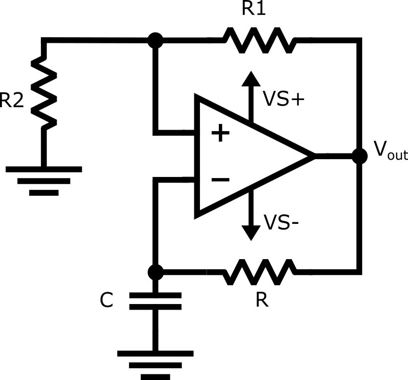
The voltage at the non-inverting pin is controlled by the output and the positive feedback network. The voltage at the inverting pin is controlled by a charging or discharging RC circuit. The capacitor will charge and discharge towards the voltage set at the non-inverting pin and when it reaches the voltage, the output will switch and the capacitor will then discharge or charge in the opposite direction. This automatic switching back and forth creates an oscillator
Video: Op Amp Oscillator
This video describes how the op amp oscillator works and derives an equation for how to calculate the frequency of the oscillator based on the R and C values
Op Amp Oscillator Practice Problems
Question 1. (Click on arrow for answer)
This is a very common opamp oscillator circuit, technically of the relaxation type:

Explain how this circuit works, and what waveforms will be measured at points A and B. Be sure to make reference to RC time constants in your explanation.
File Num: 01171
Answer
You will measure a sawtooth-like waveform at point A, and a square wave at point B.
Challenge question: explain how you might go about calculating the frequency of such a circuit, based on what you know about RC time constant circuits. Assume that the opamp can swing its output rail-to-rail, for simplicity.
Notes
This circuit is best understood by building and testing. If you use large capacitor values and/or a large-value resistor in the capacitor’s current path, the oscillation will be slow enough to analyze with a voltmeter rather than an oscilloscope.
Question 2. (Click on arrow for answer)
A variation on the common opamp relaxation oscillator design is this, which gives it variable duty cycle capability:

Explain how this circuit works, and which direction the potentiometer wiper must be moved to increase the duty cycle (more time spent with the opamp output saturated at +V and less time spent saturated at -V).
File Num: 02673
Answer
Move the wiper up to increase the duty cycle.
Notes
This circuit is best understood by building and testing. If you use large capacitor values and/or a large-value resistor in the capacitor’s current path, the oscillation will be slow enough to analyze with a voltmeter rather than an oscilloscope.
Incidentally, the Schottky diodes are not essential to this circuit’s operation, unless the expected frequency is very high. Really, the purpose of the Schottky diodes, with their low forward voltage drops (0.4 volts typical) and minimal charge storage, is to make the opamp’s job easier at every reversal of output polarity. Remember that this circuit is not exploiting negative feedback! Essentially, it is a positive feedback circuit, and every voltage drop and nonlinearity in the capacitor’s current path will have an effect on capacitor charging/discharging.
Question 3. (Click on arrow for answer)
Most operational amplifiers do not have the ability to swing their output voltages rail-to-rail. Most of those do not swing their output voltages symmetrically. That is, a typical non-rail-to-rail opamp may be able to approach one power supply rail voltage closer than the other; e.g. when powered by a +15/-15 volt split supply, the output saturates positive at +14 volts and saturates negative at -13.5 volts.
What effect do you suppose this non-symmetrical output range will have on a typical relaxation oscillator circuit such as the following, and how might you suggest we fix the problem?

File Num: 02675
Answer
The duty cycle will not be 50\%. One way to fix the problem is to do something like this:
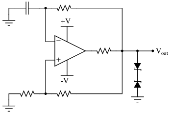
Follow-up question: explain how and why this solution works. Now you just knew I was going to ask this question the moment you saw the diagram, didn’t you?
Notes
Note that I added an additional resistor to the circuit, in series with the opamp output terminal. In some cases this is not necessary because the opamp is self-limiting in output current, but it is a good design practice nonetheless. In the event anyone ever swaps out the original opamp for a different model lacking overcurrent protection, the new opamp will not become damaged.
Question 4. (Click on arrow for answer)
Dual, or split, power supplies are very useful in opamp circuits because they allow the output voltage to rise above as well as sink below ground potential, for true AC operation. In some applications, though, it may not be practical or affordable to have a dual power supply to power your opamp circuit. In this event, you need to be able to figure out how to adapt your dual-supply circuit to single-supply operation.
A good example of such a challenge is the familiar opamp relaxation oscillator, shown here:

First, determine what would happen if we were to simply eliminate the negative portion of the dual power supply and try to run the circuit on a single supply (+V and Ground only):

Then, modify the schematic so that the circuit will run as well as it did before with the dual supply.
File Num: 02676
Answer
Here is one solution:
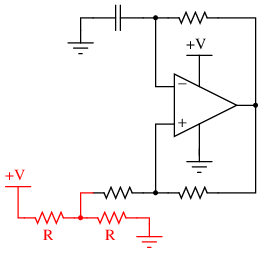
Here is another solution:

Follow-up question: now you just know what I’m going to ask next, don’t you? How do these modified circuits function?
Notes
Dual power supplies are a luxury in many real-life circumstances, and so your students will need to be able to figure out how to make opamps work in single-supply applications! Work with your students to analyze the function of the suggested solution circuit, to see how it is at once similar and different from its simpler, dual-supply forbear.
Question 5. (Click on arrow for answer)
Predict how the operation of this relaxation oscillator circuit will be affected as a result of the following faults. Consider each fault independently (i.e. one at a time, no multiple faults):

- Resistor [latex]R_1[/latex] fails open:
- Solder bridge (short) across resistor [latex]R_1[/latex]:
- Capacitor [latex]C_1[/latex] fails shorted:
- Solder bridge (short) across resistor [latex]R_2[/latex]:
- Resistor [latex]R_3[/latex] fails open:
For each of these conditions, explain why the resulting effects will occur.
File Num: 03798
Answer
- Resistor [latex]R_1[/latex] fails open: Opamp output saturates either positive or negative.
- Solder bridge (short) across resistor [latex]R_1[/latex]: Output voltage settles to 0 volts.
- Capacitor [latex]C_1[/latex] fails shorted: Opamp output saturates either positive or negative.
- Solder bridge (short) across resistor [latex]R_2[/latex]: Output voltage settles to 0 volts.
- Resistor [latex]R_3[/latex] fails open: Output voltage settles to 0 volts.
Notes
The purpose of this question is to approach the domain of circuit troubleshooting from a perspective of knowing what the fault is, rather than only knowing what the symptoms are. Although this is not necessarily a realistic perspective, it helps students build the foundational knowledge necessary to diagnose a faulted circuit from empirical data. Questions such as this should be followed (eventually) by other questions asking students to identify likely faults based on measurements.
Question 6. (Click on arrow for answer)
Identify at least two different component faults that would result in a change in duty cycle for this oscillator circuit:

File Num: 03799
Answer
A short in either of the two diodes would cause the duty cycle to change.
Follow-up question: what would happen if either of these two diodes failed open?
Notes
Ask your students to explain why the duty cycle would change as a result of either diode failing shorted. This is a good opportunity to further explore the operation of this oscillator circuit.
Contributors
Contributors to this chapter are listed in chronological order of their contributions, from most recent to first.
David Williams (2022): First edits including videos
Practice Problem Copyright
All practice problems with a file num less than 4100 are Copyright 2003, Tony R. Kuphaldt, released under the Creative Commons Attribution License (v 1.0). All other files are Copyright 2022, David Williams, released under the Creative Commons Attribution License (V 4.0) This means you may do almost anything with this work, so long as you give proper credit.
To view a copy of the license, visit https://creativecommons.org/licenses/by/1.0/, or https://creativecommons.org/licenses/by/4.0/, or send a letter to Creative Commons, 559 Nathan Abbott Way, Stanford, California 94305, USA. The terms and conditions of this license allow for free copying, distribution, and/or modification of all licensed works by the general public.


 [latex]V_{UT}[/latex] = \hskip 80pt [latex]V_{LT}[/latex] =
 [latex]V_{UT}[/latex] = \hskip 80pt [latex]V_{LT}[/latex] =
 [latex]V_{UT}[/latex] = \hskip 80pt [latex]V_{LT}[/latex] =


